Follow Us:

Browse Flowering Elbow

Latest Blog Entries

Outside FE

Automated door from an old windscreen wiper motor

Posted: March 8th, 2023, by Bongo

In this one, we’re making an automatic door for the chicken coop using an old wiper motor some scrap metal, and an Arduino. Before we started keeping chickens we knew we didn’t really want to be tied to getting up at the crack of dawn, or always being at home by dark to put them away. You can get commercial autodoors as pre-made kits to fit on the coop, and indeed we already had experience with one that used a linear actuator – although it was modified so it operated the door to the goose shed (they require a much bigger opening than chickens). Anyway watch the video here, and we’ll give a few extra details below.
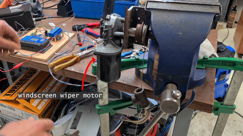
The humble Wiper Motor

Upcycled wiper motors work well for this project because they come with speed-reducing gearing, are very robust, and have ample torque to move a door (even a big heavy door). That, and used ones are plentiful and cheap to get hold of at a scrappy or on e-bay! They are fairly standardized and usually have five wires. Two of these we can ignore for this kind of project (the two you can trace to the gearbox area). The others are a common (the white one in our case), a high, and a lower speed contact.

On the output, most of them, so far as I can tell, come with a tapered splined shaft, that conveniently ends with a male M8 thread. This can be joined to a host of different things. In our case we drilled and tapped an old keyed shaft and v-belt pulley that will form a ‘winding spindle’, to raise and lower the coop door. We happened to have this part but one could just as easily use a wooden spindle, which could be attached with an 8mm pronged insert nut. Another coupling method might be to use an M8 coupling nut (the kind designed for joining 8mm threaded rod).

The Brains

There was a LOT of tweaking to the design, which started off using a relay board to switch the wiper motor, and ended up using a IBT 2 motor driver, as after testing, I deemed even the slower speed of the wiper motor to be too fast. The IBT 2 has the advantage of easily controlling the speed via a pulse width modulation signal from the Arduino. This enables us to easily set the ‘motorSpeed’ in the code, and it lets us easily make the speed much less on the way down (closing) as the way up (opening), to lessen chicken squash risk… It can even smoothly accelerate and decelerate to the selected speed. The only downside is that it makes a bit of a high-pitched noise that’s not super pleasant, but the chickens don’t seem to mind.

The IBT 2 is a super cheap motor driver module (I got one for less than £5). It uses two BTS7960 half bride chips and comes with a bolt-on heatsink (which I suspect would get very hot if you ran it anything like the claimed 43amps (I’m skeptical of this figure as I have seen identical-looking modules online that claim 30A). The module’s 4 screw terminal connects to the two 12VDC supply wires (from the solar charge controller in my case), and the two wires going to the wiper motor – simple!
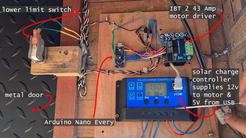
The only other important components are:

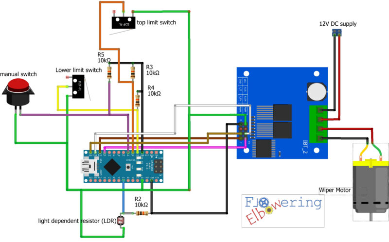
  • the light dependent resistor (LDR) – which senses the light levels so we can close at dusk and open at dawn. The one I’m using is the GL5516 Light Dependent Resistor Photoresistor which was £2.75 for a pack of 10. I couldn’t find them individually, which as it turns out, was just as well, as I managed to snap the leg off the first one I was using.
  • the two limit switches which tell the system if the door is open or closed. They are salvaged from an old microwave (a plentiful source of microswitches).
  • a manual switch. This can be activated from outside the coop and is used to manually override, opening or closing the door depending on its current state.
  • Four 10KOhm pull-down resistors. I’m fairly sure we could have done without at least 3 of these by using the Arduino’s onboard pull-up facility. There is no internal pull-down, only ‘pull-up’ so that would involve code modifications and I only found out about the possibility when I was mostly finished.
The electronics all get mounted inside the coop out of the elements and get covered over with a wooden box/cover. It’s powered by an old 12V battery (salvaged from a skipped electric wheelchair), which is kept charged with a second hand 20W solar panel, which sits on top of the chickens’ enclosure/run. The solar charge controller that should keep the battery from overcharging is cheap (under£20). I was skeptical, as the battery was already fairly old and tired, but thus far it has seen us through autumn and a Welsh winter without tons of sun…

The Code

I have tried to comment in the code to make it easy to understand, so the best way to get a handle on it is to have a quick look through. It can be downloaded free here on our Ko-fi page.

Here are some highlights though:

The code calibrates the brightness sensor (LDR) by setting the maximum and minimum voltages that correspond to minimum and maximum brightness. It also sets the thresholds for when the door should open and close based on the amount of light detected. This is a percentage value and can be tweaked by adjusting the variables: “brightnessLowThreshold” and “brightnessHighThreshold”.

Hysteresis variables are used to prevent false triggering of the door (say if a shadow, or the beam of a torch, falls across the LDR). The code also sets a timer to ensure that if the limit switch fails for any reason the wiper motor won’t carry on going re-reeling in the wire and opening the door again. If it kept going it would have the potential to damage things…

The setup initializes the pins, while the loop reads the state of the switches and the brightness sensor. It also includes an initialization step to open the door when the system is first turned on. If the door is not in the fully opened position, it will continue to open the door until the limit switch is triggered. The system then measures the brightness and decides whether to open or close the door based on the thresholds set. Finally, the loop includes a manual control button that increments the currentSwitchState variable whenever it is pressed.

Well, that’s about it, the code and circuit diagram are free and on the ko-fi page, any questions please get in touch in the comments on the youtube vid (checked more often than here).
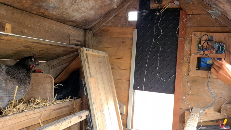
Prototyping
installing… All this gets covered with an enclosure.

I did not expect to be using the CNC like this

Posted: December 30th, 2022, by Bongo

A two-part CNC video hit the tubes recently. It documents some of our adventures learning to use this beast we have created. The truth is that when we were scavenging parts and building it (see the CNC machine design & make), we didn’t really know exactly how we would use it. It makes pro-CNC builders cringe. I mean we had some ideas: we know we wanted it to help us make more wacky furniture and other ‘functional-art’ from upcycled materials, for example. Apart from that, the goal was to make it ‘very capable’, perhaps even able to machine steel, while still big enough to fit a 4x8ft sheet on the bed. Versatility like this doesn’t come easy. As you get to larger format CNC’s, like the 4x8ft routers, it becomes much harder to maintain enough rigidity to make good cuts in metals.

Higher z axis clearance, which gives the ability to machine much thicker lumps of material, make the situation even more difficult in terms of rigidity. In the video we do some deflection tests on the machine to confirm this.

I always knew this was going to be a serious problem with this design, but had thought that the way the z-plate (which carries the spindle) rides up and down on its linear guides (which are THK SHS20’s BTW) in combination with cunning work holding, would allow me to get round this conundrum. By having raised up, structural sides which carry the gantry, this machine is comparatively very rigid near the top of the z travel, where the moment forces that attempt to exert leverage on the gantry with the length of the z plate are minimized (as in the pic below).

In this example, it’s the addition of the relatively tall mechanists vice and its swiveling base that really raises the workpiece up to where the spindle mount, the lower linear guide bearing and the long oversized SHS35 bearing blocks are in line. The massive concrete sides and the gantry’s strategic epoxy granite also help keep vibrations to a minimum.

One weakness of the current build is the baseboard; an 18mm sheet of ply under an 18mm sheet of MDF. It has certainly made a good learning platform. To my shame, more than once, I have accidentally plunged non-spinning endmills right up to the collet, through the relatively soft material, the servo drive only throwing an error as the collet nut tries to smash through! Anyway, for milling metals, the wood-based spoilboard has the twin downside of deflecting noticeably under higher loads, and not dealing well with any kind of moisture (think mist or flood coolant). As you see in the pic above a temporary semi-solution was using this sheet metal tray to contain cutting fluid.

To begin with, we were using a cheap amazon mist cooler. It did help: in the video for example, we use it to mill steel with decent results. It has a serious drawback. It was VERY inconsistent. Fiddling with the valves that control air and fluid flow would occasionally give you the perfect amount of cutting fluid and air-blast. More commonly it would spray coolant everywhere uncontrollably, or fill the shop with a dense fog, or stop putting out oil and let the cutter run dry – most often all three in the same cut!

It was changed for a DIY fog-buster type deal, which you can see in the video. It works much better to give minimal quantity lubrication (MQL), and blasts the chips out the way to prevent re-cutting.

In the second video in this little series, we have a go at milling slate (!) and steel and using the CNC as a surface grinder/ knife sharpener. Not a sensible operation, but one that involves some fun jig making, dust shoe creation, and us ultimately learning a lot.

Click any of the pics below to watch the video:

Cutting Steel with the CNC.
Nice blue chips

Nice blue chips, indicating a reasonable amount of heat being carried off by the swarf, and decent feed and speed.

The four servo drives, Ethernet smoothstepper, relay board, 5 & 24V DC supplies, break out board and VFD
Flattening slate using a carbide surfacing bit designed for wood.

The DIY CNC Router cuts steel!

Posted: May 10th, 2022, by Bongo

Making the CNC machine has been an ongoing side project for a long time. It’s a machine that is able to flatten slabs too wide for the thicknesser, cut out intricate shapes in sheet materials, like plywood, engrave letters and pictures, shape 3D objects, mill flat accurate surfaces into aluminum and steel, use a drag-knife to cut out materials like card, cotton, leather, vinyl, etc.) and even draw big line art pictures with a pen. You can see the CNC beast being made (and tested!) in this video.

The machine’s frame is made from old I-beams, that we got from e-bay, partially filled with glass & steel-reinforced concrete. This both adds vibration damping and some rigidity to the I-beam – which is otherwise not very good at resisting twisting forces (although the endplates and midsection bracing also help with this).

One couldn’t just use regular garden-variety concrete for a precision machine tool like this because it would shrink and move way too much. We spent a l o n g time researching concrete mix design to get suitably stable and strong ‘machine tool grade’ concrete. It also added about three months onto the build while we waited for the mix to cure enough, and then dry enough to be sealed with paint.

Of course, it’s not like we were really ‘waiting’ as we had loads of other projects on the go, including making the rather unusual gantry! Because the gantry is whizzing back and forth along the length of the frame, it has very different properties from the frame. Instead of being very stiff and vibration damped at all costs, something the frame achieves with steel and concrete (lots of mass!), the gantry is all about stiffness to weight ratio. Therefore we use aluminum extrusion (from a retired old stair-lift), which has good strength to weight, and strategic epoxy granite (unparalleled vibration damping), as well as our own DIY aluminum castings, to form the gantry.

The video about the unusual gantry

For more, here’s a video all about how the gantry goes together.

The gantry is driven by a twin servo, ‘rotating ballnut’ design. This took some tweaking (see these videos), but has the big advantage of helping to prevent whip (a problem where the ballscrews violently wiggle about, causing excessive wear to the bearings) at higher speeds, and much reducing the rotating mass, and therefore the inertia of the system. All ultimately lead to faster and more efficient movement.

Watch the video about the rotating ballnut design.

The z axis (the one that moves the spindle up and down) is made from old alloy wheel we melted in the furnace and cast to shape. We refined our casting process a lot by doing these relatively large castings. Indeed if you are interested in home shop casting there are a lot of tips in this video – which also shows the z axis spindle plate being cast:

Tips for making actually good aluminum castings in the home shop.

There is a great deal more to say about the CNC machine, in fact, we are in the process of writing a book/guide to help would-be DIY CNC builders… In the meantime, we’d love to hear your thoughts or questions, either here or in the comments on youtube. If you would like to play with the 3D CAD model of the CNC we build you can find that here: https://ko-fi.com/floweringelbow/shop

A New Book about Chainsaw Milling

Posted: May 9th, 2022, by Bongo

Nice slabs with a chainsaw – sounds easy! But for us, it has been a long journey, with triumphs yes, but also plenty of mistakes too. We have learned so much about milling up fallen trees we needed to write a book to share it!

Available from the ko-fi store here: https://ko-fi.com/s/dd5b46e8a8

The aim is to let the reader leapfrog some of the common pitfalls and problems encountered when chainsaw milling, and give enough detailed advice that the reader can soon make the finest quality boards possible, with their own Alaskan style chainsaw mill.

How to make Slug-Proof Raised Beds, uncommon yet simple design

Posted: November 1st, 2020, by Bongo

In this one we show how we made an unusual but very simple design for a slug-proof raised bed vegetable patch. These raised beds are very cheap, as we made them from chainsaw milling off cuts (slabwood) and branches that would have been firewood.

The construction is very straightforward. and primarily done with a chainsaw! The idea is to use the top and bottom slabs, that have one awkward irregular face and therefore will not stack easily for drying.

Chainsaw milling slabs to be used for raised bed sides

Even the mitre joints on the ends are …Continue reading »

Posts that see out the century! How to make your own rot proof timber

Posted: October 26th, 2020, by Bongo

When you put in a new gate post, durability is a must have, and many people, myself included, have not been satisfied with regular pressure treated or tanalised spruce posts. They rot quickly at the interface between the ground and the air, which is where fungus and insects thrive, having both moisture and oxygen. This video describes three attempts to counteract short-lived timber posts (as well as some chainsaw milling tips).

1. Choose the species of timber

There are many naturally durable kinds of timber. In this instance we are chainsaw milling White Oak. Other long lasting timbers include Black Locust, Osage Orange, Cedar, Hawthorn, Chestnut, etc. Using a durable timber species will mean the treatment of the wood can be a lot less toxic.

In general, even on these species, the sapwood is much less durable, and along with the bark, is worth removing.

Manoeuvring about with timber this size can be quite challenging. Levers are handy!

For the first time we also experimented with an exceptionally primitive DIY Vertical CS Mill jig. Surprisingly it worked quite well!

In terms of actually transporting the cut posts, 8ft long sections of 8″x8″ and 9″ x 8″ oak heartwood, we used the quad and trailer, as the ground is too boggy to use much else. So despite spending a reasonable amount of time on the fixer-upper JCB (more on that another time), we couldn’t use that in this instance.

No more than two at a time seemed prudent!

2. Treatment (FIRE!)

The kind of treatment tested here is one that has been used for centuries. It involves charring the timber, creating a protective torrefied layer, that is harder than the un-charred wood (which is incidentally similar to the way our Palaeolithic ancestors hardened their sharpened sticks to make spear-like weapons). Outside this hardened torrefied layer is the carbonized char, which should also be unappealing to fungus and insects.

We used the experimental rocket stove to do the charring, supporting the posts on a roller attached to a small scaffolding tower… It worked well.

The process exists in many cultures, but is probably most well known in Japan, where ancient wooden temples, with the treatment, still exist today. In Japan, the treatment is known as ‘shou-sugi-ban’.

It’s worth noting that this is an experiment – some posts we charred and some we didn’t – let’s see in 20 years how things are going…

Update: There has been an interesting study published 2021 suggesting that there are NO durability benefits to charring in most wood species (see here https://www.mdpi.com/1999-4907/12/9/1262).

We scraped away the very outermost layer of char on our posts. Why? Well for the explanation and the other details, like how deep to char etc. just watch the video :)

3. Installing the Gate Posts & Moisture Management

The last step to getting a strong, long lasting post, is to put it in right! Depending on the local ground conditions the tends to mean ‘rocking’ it solid. That is digging a hole big enough to fit the post, and a surrounding layer of compacted stones, that will provide excellent drainage.

Again to see our method on this, just watch the vid, but basically it involves some rather vigorous compacting of rocks round the post. adding another layer, compacting again, etc. etc. The rocks come slightly proud of ground level and slant away from the post to cast water away…

Finishing Touches

We added a little copper hat as we had some scraps knocking about anyway, but anything that will protect the exposed end grain on top and send water off will help. That could be as simple as cutting a chamfer on top, or nailing on a small wooden board…

Anywhere metal is in contact with the oak, such as the gate hinges and closure, it’s a nice idea to insulate with some thin plastic – this prevents it reacting with the tannins in the oak and corroding faster (and making unsightly black stains down the oak).

How to Drive for free: Bio-tuning a VW Caddy Van

Posted: March 28th, 2020, by Bongo

This tale is about trying to run carbon-neutral by converting our 1.9 tdi PD diesel engine to run on straight vegetable oil.

Click to watch the Grease wagon making video

It’s an experimental and somewhat controversial procedure, which is why we hadn’t done it long ago! We are using a conversion kit from a company called Biotuning, here in the UK. The basic idea is to add a second fuel tank, a heated fuel filter, another heat exchanger, and two solenoid valves, that control which fuel is delivered to the engine.

There is a complete animated explanation of the two tank veg oil system in the video, but here’s the general idea:

The diagram shows the system valves set in the veg-oil running mode.

Vegetable oil Viscosity

The reason it’s inadvisable to just shove veg oil straight into your tank, without modifications, is that it is …Continue reading »

How to make a Garden Bench with the Chainsaw

Posted: February 29th, 2020, by Bongo

We made this oaken beauty as a gift to say thank you to our neighbours, who were kind enough to let us chainsaw mill wood from a massive poplar tree that fell on their house in a storm (see here for that story).

How to make a garden bench

As usual the start to finish build video has more details, but lets look at the basics of construction.

Chainsaw Milling Oak

It’s nice to already have a rough idea in mind when milling up logs, especially if your planning to use the wood green, or to make something a bit unusual, like this bench.

Here we are using the mill to cut a curved …Continue reading »

Reuse a Washing Machine Motor, Make an upcycled multi-tool!

Posted: June 4th, 2019, by Bongo

The last three videos have all been about using old washing machine parts! Two have shown the de-construction and upcycling of the bearings and frame, into something I could use as a multi purpose rotary machine, and the latest one, is all about the options faced by the maker who wants to control a motor taken from an old washing machine.

The frame of this old washing machine hoses the drive components for a spinning platter, with some space left over for shelves and storage.

Ages ago I made this wood lathe which was driven by one of the ubiquitous brushed universal washing machine motors. I used a simple triac based control circuit. This is a circuit that has a nice low part count and is very easy to construct using a single piece of perfboard. What I like about this controller is it’s …Continue reading »